
Why SMART Homebuyers Choose Us
It's Your Home - It's Your Money - It's Your Family
YOUR FAMILY DESERVES THE BEST.
The Synopsis of "Why Choose Us"
You, and your new home, are our ONLY focus on your inspection day (1 house per day).
We take the time to document as many issues in a home as possible (We average 70 issues in our reports).
Schedule more time with our clients during and after the inspection.
We average 3 hours on site.
We schedule 5 hours because we don't know what we will find.
We offer a 1.5 hour Zoom session for Cost to Cures and contractor referrals.
Use more professional equipment to be more definitive in our findings.
Be the highest rated inspection company in Chicagoland!
charlie's why
The clients that choose us don’t settle. They dig into the details, vet the reviews, and ensure they’re working with professionals who deliver unmatched value. Sound like you? Then let us show you what makes us the best. By pairing your diligence with our expertise, we create a team focused on delivering the information you need to negotiate smartly. This entire page is devoted to why we are the best choice. You might be thinking well can't any home inspector do what you do? They can, they just don't

Choosing anyone but the best harms your investment. We unapologetically stand as the top home inspectors in Chicagoland, delivering expertise you can’t afford to miss.
Awards For Excellence

Expertise
Best Home Inspection Companies Serving Chicago

Three Best Rated
Expert-recommended Top 3 Home Inspections in Chicago

Yelp
5.0 Rated on Yelp
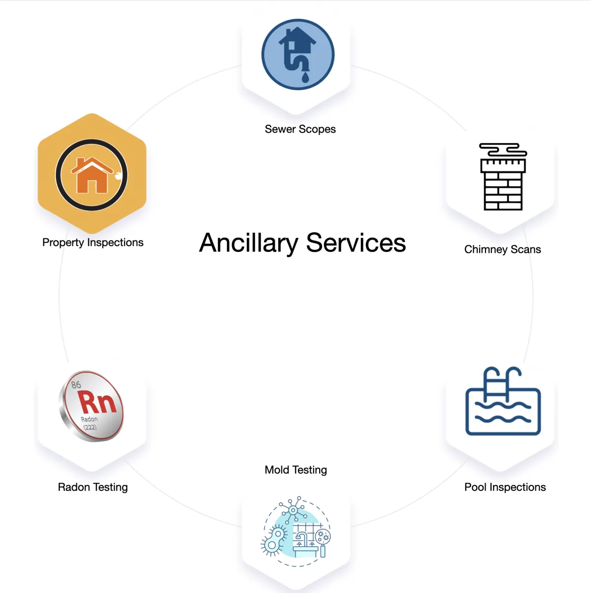
OUR SERVICES
Detailed pricing & information to help you decide if these additional options are a good use of your money. I believe in knowing what the risks, along with the cost, to determine if this is a good value. Scroll down for more detailed pricing.
KNOW HOW
Home/Townhouses - Starting at $550
Condo Inspections - Starting at $450
State Farm Insurance Inspections - Starting at $550
2 to 4 Units - 2 = $700, 3 = $900, 4 = $1,000
Sewer Scopes - $350
Chimney Scans - $250 Plus $150 Each Additional Flue
Pool Inspections - $350
Mold Testing - Starting at $350
Radon Testing - $270
Termite Inspections - VA Loans Only - Comped to Vets
Irrigation Inspections - $150
We assume you are looking at other companies, so here is a chart that compares services and price.
There is a difference so ask if they use, or provide, what we do.
Again, we do want to work for you. We do feel we create the most detailed inspection reports and we have the best equipment that is used by skilled professionals who are committed and passionate about their work. We do not believe that just anyone can do this job properly. Which is why I personally approve every inspector who works under our name. I will not allow our reputation to be tarnished. We also provide the best warranties should that unpleasant surprise happen.
Warranties & Additional Protection
We believe in transparency and want to ensure you are fully protected during your home-buying journey. While we strive for excellence, it is important to understand the realities of a home inspection and why we strongly encourage purchasing additional protection.
The Reality of Home Inspections
No home inspector is perfect; hidden or concealed issues exist in every home, and some conditions simply cannot be detected during a visual, non-invasive inspection. Mistakes can happen because inspectors are human. Furthermore, home inspection companies are not insurance companies. Our professional fees are designed to cover a thorough, professional evaluation of the property’s current condition, not to act as an underwriting service for future repairs. We do not have the profit markup necessary to provide a full-service warranty as part of our standard inspection fee.
Optional Protection Plans
For clients seeking financial peace of mind, we recommend two distinct options:
InterNACHI Inspection Warranty $50.00 Fee: This is a short-term protection plan that generally lasts for 90 days from closing or 120 days from the inspection, whichever comes first. It provides reimbursement for specific eligible repairs for appliances, electrical, plumbing, HVAC, and structural elements. Notably, the Master plan has no age limits on appliances and no deductibles.
Achosa Home Warranty Purchased Separately: For those wanting longer-term, comprehensive coverage, Achosa offers annual service contracts (available for 12, 18, 24, or 36 months) for major home systems and appliances. Achosa is unique because it gives you the "power to choose" your own licensed contractors for all required services rather than requiring you to use a pre-assigned provider.
Our Exclusive Commitment
To demonstrate our commitment to your protection, if you purchase the InterNACHI Warranty through us, we will match anything they pay out as a claim, provided the total amount does not exceed the actual cost of the repair or replacement. We want to be your partner in ensuring that a "bad day" or a missed hidden defect does not become a financial burden for you. You must purchase the Warranty at the time of the inspection.
Our Pricing Structure
How Our Math Works
We want to be transparent when figuring out our pricing. But we do charge different fees for different types, and sizes, of the properties.
Single Family/Townhouses
Our base fee for houses up to 2,500 SqFt is $600.00
Our "Photo-Upload" discount is -$50.00. Everyone should take this discount. The intent is to plant the seed to judge us when all is said and done.
PLEASE TAKE THIS DISCOUNT - WE DON'T ENFORCE IT.
Add $75 for over 2,500 SqFt and an additional $75 for every additional 500 SqFt. We go by the largest SqFt. Either the listing or what is on the tax records.
Condos where we skip the roof, exterior, and common areas of the building start at $500 with the same increases as the Single Family/Townhouses for over 2,500 SqFt.
Don't forget the Photo discount.
Multi-Family 2 to 4 Units - 2 = $700, 3 = $900, 4 = $1,000
Don't forget the Photo discount.
Commercial Properties are on a case by case basis.
Photo Upload Discount: We give this to every client. The purpose of this discount to to plant the idea that we want you to judge us by leaving a review after everything is done, the report is delivered, and our business is complete. Other inspectors believe I am stupid for offering this. I get constantly asked - What happens when someone is going to leave a bad review? This may sound a bit hokey, but I believe most people are honest. I am sure there are bad people out there. I believe that our clients will leave a positive review if our inspectors, and myself, truly go out of our way to deliver more than what we promise to our clients. We are not perfect. We make mistakes. I don't judge people on the mistakes that they make, I judge them on how they handle the mistakes. We believe in doing the right thing, at the right time, for the right reason, and the right way. If you think about this a bit, you will realize that angry people do angry things. Making clients angry will motivate them to leave a negative review. But we really don't have many negative reviews. At the time of writing this, we have one three star and 2 four star reviews. All the rest, over 1,800, are five stars. The photos that you see with them are because of this discount. This is how we prove our reviews are real and not purchased. Think about how confident I am in our inspectors, our services, our reports, and our processes to risk our reputation by doing this sort of a discount. I will not let anyone work under our name who can tarnish that reputation.
Read The Reviews Yourself
Google Northbrook Office: https://maps.app.goo.gl/xtve2bHgqBtgdCvPA
Google Chicago Office: https://maps.app.goo.gl/YMq9BARJHostYeCX9
Yelp Northbrook Office: https://bit.ly/YelpNorthbrook
Yelp Chicago Office: https://bit.ly/YelpCHIChicago
Facebook: https://www.facebook.com/ChicagoInspections/reviews
Add-On Services
Radon Testing: $270
What is Radon? Radon is a colorless, odorless gas that can cause lung cancer. It’s the second leading cause of lung cancer in the U.S.
Risks: High radon levels are common in Illinois. The State of Illinois records all radon tests performed by licensed professionals.
Rewards: Testing ensures your home is safe. If high levels are found, mitigation systems can reduce radon to safe levels.
AI Charlie: Ask AI Charlie for radon results in your zip code. It will provide the risks, rewards, and historical data immediately 24/7. https://bit.ly/AI-Charlie
Sewer Scope Inspection: $350
What is a Sewer Scope? A camera inspection of the sewer line to identify blockages, cracks, dips/bellies, or tree root intrusions.
Risks:
Clay Tile Sewers: High probability of problems due to settlement and root intrusion.
PVC Sewers: Low probability of problems but not immune to issues.
Rewards: Identifying sewer problems early can save you thousands in repairs and get you started on a maintenance plan to manage tree roots. They are very common.
Mold Inspection: Starting at $350
What is Mold? Mold is a fungus that grows in damp environments and can cause health issues.
Risks:
Mold can cause allergies, respiratory problems, and structural damage.
Rewards:
Testing identifies mold growth and moisture sources, allowing you to address the problem before it worsens.
Our Philosophy on Mold Testing:
Mold air testing should be done if a person living in the home has an immune deficiency, asthma, or mold allergies.
IMPORTANT: If we see visible mold, we will photograph it, use a thermal imager and moisture meter (if possible/needed) to prove, or disprove the presence of water. This will be done during our normal inspection. We do NOT recommend testing if we see visible signs of mold. We recommend cleaning it first and then testing to confirm it was cleaned properly.
The key to controlling mold is controlling water. We’ll help you identify and address moisture issues to prevent future growth. IN SHORT, I DO NOT BELIEVE IN AIR SAMPLING FOR MOLD UNLESS YOU HAVE A HEALTH ISSUE AND WANT TO MAKE SURE THE AIR IS CLEAN.
Chimney Scan: Starting at $250
What is a Chimney Scan? A camera inspection of the chimney to check for blockages, cracks, or creosote buildup.
Risks:
Clay Tile Flues: Often have issues that average $10,000 in repairs.
Metal Flues: Rarely have issues and are not as expensive to fix.
Pricing: $250 for the first flue and $150 for each additional flue.
Pool Inspection: $350
What is a Pool Inspection? Evaluates the pool’s structure, equipment, and safety features.
Risks:
Cracks, leaks, or faulty equipment can lead to costly repairs.
Rewards:
Ensures your pool is safe and in good working condition.
Termite Inspection: $150
We do not want any client to pay for this service. When this is added to the order, the only thing we do differently is complete a NPMA-33 form that is required for VA Mortgages. We are going to be looking at the entire visible portion of the structure during our normal home inspection. We will photograph, and document, what we see. This includes active termites, past damage, and signs of mitigation. If you are getting a VA Mortgage, please let us know and we will comp this fee. It is our small way of saying "Thank You". It does need to show on the invoice that you will give to your lender.
What is a Termite Inspection? Checks for termites and other wood destroying insects.
Risks: Termites can cause significant structural damage if left untreated.
Rewards: Early detection can save you thousands in repair costs.
What Makes Us Different?
1. No Upselling:
We don’t believe in pressuring clients. Our goal is to educate and empower you to make informed decisions. If we recommend an add-on service, it’s because we genuinely believe it’s in your best interest. It really comes down to the risks vs. the rewards.
2. Advanced Tools & Technology
We invest in the latest equipment to provide the most accurate inspection possible. While no inspection can guarantee that every issue will be found, our process signicfiantly lowers the risk of missing problems.
3. Personalized Support
Charlie personally reviews every report with you to help set priorities, answer questions, and guide you through the next steps. It’s like having a trusted advisor by your side.
4. One Inspection Per Inspector Per Day
We don’t rush. Each inspector focuses on one inspection per day, ensuring they have the time and attention to thoroughly evaluate your home.
5. Over 1,800 Five-Star Reviews
Our clients love us—and it shows. We’re proud to be the highest-rated home inspection company in Chicagoland.
Next Steps
Ready to Schedule? Click here to book your inspection: https://bit.ly/CHIsched.
Have Technical Questions? Ask AI Charlie for instant answers: https://bit.ly/AI-Charlie.
Need More Information? Simply text or call us. We’re here to help! (224) 332-2727
Buying a home is one of the biggest decisions you’ll ever make. We respect that, and we’re committed to supporting you every step of the way. With Chicagoland Home Inspectors, you’re not just getting an inspection—you’re getting peace of mind. Let’s get it right—together.
1. Thorough & Diligent Inspections
We take our time to ensure a comprehensive evaluation of your home. Our inspectors spend 3-5 hours on-site, depending on the size and condition of the home. On average, we document 70 issues per home, and our process is designed to significantly reduce the chances of missing problems. The bottom line is this: The faster you go, the more you miss.
That’s why we:
• Each Inspector performs only one inspection per day. (This is a big deal)
• Focus entirely on the house and our clients during the inspection.
• Write our reports off-site to ensure accuracy and attention to detail.
2. Advanced Tools & Technology
We use state-of-the-art equipment to provide the most accurate inspection possible. Our tools include:
• Thermal Imaging Cameras: To identify drafts, water intrusion, and heat flow issues in ducts.
• Moisture Meters: To detect moisture that could lead to mold or structural damage.
• Combustion Analyzers: To test furnaces for safe and efficient operation.
• Drones: As a backup for roof inspections when walking the roof isn’t safe or feasible.
While no inspection can guarantee that every issue will be found, our process significantly lowers the risk of missing problems.
3. Comprehensive Reports
Our goal is to create a long, accurate list of issues with clear explanations of:
• How serious the issue is.
• Options to correct the issue.
• How much of a priority the issue is to address.
Every report includes:
• High-Resolution Photos and Videos: To visually document the condition of the home. Our goal is to prove everything is in good shape, but if it’s not, we make it easy to identify problems and offer solutions.
• Zoom Consultation: A personalized session with another inspector to review the report in detail, discuss options, and show you how to use cost calculators for repairs.
• We Aim to Deliver Reports the Same Day: inspections in the morning, report writing in the afternoon, and delivery by evening. In rare cases, reports may be completed the next morning, and your inspector will let you know if that’s the case.
4. Proven Track Record
With over 1,800 5-star reviews, our reputation speaks for itself. Homebuyers, real estate agents, and sellers trust us to deliver honest, reliable, th and professional service.
Why Our Reviews Matter: We know that some inspectors purchase fake reviews to boost their ratings. We don’t condone this practice—it’s dishonest and unfair to clients. The only way to prove our reviews are real is to invite every client to leave a review. Here’s how we prove our reviews are genuine:
• We Invite Every Client to Leave a Review: After your inspection, we’ll ask you to share your experience. We don’t cherry-pick clients—everyone gets the same opportunity.
• No Discounts for Reviews: While we offer a photo upload discount (included in the prices above), we never offer discounts for reviews. Review sites frown on this practice and would penalize us.
• Confidence in Our Process: Angry clients would leave negative reviews if we didn’t deliver on our promises. The fact that we invite every client to review us—and still maintain over 1,800 5-star reviews—shows how confident we are in our people, our process, and our reports.
Our Inspection Process.
Step 1: Schedule Your Inspection
• Booking is easy! Click here to schedule: https://bit.ly/CHIsched
Confirm Your Appointment: After scheduling, you’ll need to sign the agreement and pay the initial inspection fee within the first two hours to confirm your appointment. Please do not make an appointment until the time is verified and confirmed with all parties involved. Why do we do this. We are in demand and our schedule is typically full. We have had cancellations at the last minute. This harms our inspectors, and our company. We want everyone involved to have some "skin in the game". We do have a cancellation policy explained below. We do enforce this policy.
Payment Options:
Preferred Methods: Zelle or Venmo (no fees for you or us).
Credit Cards: Accepted, but a 4% transaction fee will be added to cover processing costs.
We don’t want to pay these fees, and we don’t want you to pay them either. We encourage using Zelle or Venmo.
Cancellation Policy:
• Less than 48 hours notice: 50% of the inspection fee will be charged.
• Less than 24 hours notice: 100% of the inspection fee will be charged.
• Reminder: We’ll send you a confirmation and a reminder before your inspection.
Step 2: Thorough On-Site Inspection
• Our inspectors spend 3-5 hours on-site, depending on the size and condition of the home and your curiosity.
If there are a lot of issues, we want to stay and document them all.
If you want to discuss the issues, we will stay and answer your questions.
IMPORTANT: Do not let anyone rush you.
• We inspect all major systems and components, including:
-Roof, Attic, and Exterior: Shingles, flashing, gutters, siding, and drainage.
-Foundation and Structure: Cracks, settling, and structural integrity.
-Electrical Systems: Wiring, panels, outlets, and safety hazards.
-Plumbing Systems: Leaks, water pressure, and pipe condition.
-HVAC Systems: Heating, cooling, and ventilation efficiency.
-Interior: Floors, walls, ceilings, windows, and doors.
Step 3: Detailed Report & Consultation and Guidance
• Same-Day Delivery Goal: We aim to deliver your report the same day. Inspections are completed in the morning, reports are written in the afternoon, and delivered by evening. In rare cases, reports may be completed the next morning, and your inspector will let you know if that’s the case.
• Final Invoice: The final bill may change if, with your permission, we add or remove extra services during the inspection. A final invoice will be sent, and payment must be made before the report is released.
• Zoom Consultation: Schedule a personalized session with one of our inspectors to review the report, discuss findings, and answer your questions.
Prices are when included with a home inspection.
"We know that there is not one other company that uses the tools that we do, provides the customer service that we do, and has as good of a reputation that we have"
If you don’t feel we offer the best service for the price, please reach out to me. I want your business.
Ask ALL Inspectors These Questions.
How Many Inspections Does Your Inspector Schedule in a Day?
Our home inspectors complete one inspection per day to maintain focus and precision. Each inspection involves three main tasks: examining the home, communicating with the client, and preparing the report. Performing all three simultaneously on-site would compromise the quality of each task. Therefore, we do not complete the report on-site. Instead, our inspectors focus on your home and use equipment to conduct a thorough assessment.For most houses, we spend around three hours on the inspection. High-rise condominiums generally take less time since elements like the roof, exterior, structure, and shared areas are not part of the inspection. After inspecting, we spend another two to three hours documenting the findings. Including travel time, this fills a full day. Our inspectors do not perform evening inspections, as this is a full-time job, and they prioritize time at home with their families.Some companies handle two to three inspections in a day, which typically results in one to two hours spent at each property. Moving quickly between jobs can lead to missed issues, which may later become problems for the homeowner. Our approach ensures we examine each home carefully and completely.
How Many Reviews Does the Inspector Have?
Every home inspector and website claims to be the best. Many inspectors hesitate about reviews, but our inspectors approach them differently. Our goal from the start of each inspection is to make a strong impression on you. We focus on a process that is thorough, accurate, and rooted in professionalism. Our aim is for you to feel confident in our work, motivated to share your experience through a review. We recognize that inviting feedback places us in a position of accountability, but we value this openness. We encourage you to include a photo with your review, as it helps us demonstrate the authenticity of our client feedback.
Can I Attend the Home Inspection?
Yes, we encourage clients to attend the home inspection. Attending allows you to observe the process, ask questions, and gain a better understanding of the property's condition. It is one thing to read a written report, but the real value is having the conversation about the issues in the home and discussing those issues with the home inspector when everything is right in front of you. It's an excellent opportunity to learn about maintenance and potential issues firsthand. If you cannot attend in person, you can still participate by scheduling a remote video walkthrough with our inspector. We aim to make the inspection process as transparent and informative as possible to ensure your peace of mind.
Does the Inspector Walk on Roofs?
Our inspectors in Chicago make every attempt to walk on a roof. Plain and simple, It’s just the best way to inspect it. Sometimes, however, this is not an option. Height, slope, snow, winds, and rain can make going on the roof dangerous. If the inspector cannot walk on the roof, we will take a series of high-resolution pictures from different angles so our inspectors can document the conditions. We have staff on hand with Remote Pilot Certificate Part 107 from the FAA. This is the certificate required for anyone using drones for commercial use. Our drones are equipped with a 4K camera which allows us to take the clearest shots available. If we cannot fly, we will send someone back when we are allowed to fly. We will do what we can to get the best pictures of the roof.
How Does the Inspector Check the Furnace?
When most inspectors just turn on the furnace, they see if it produces heat. Our home inspectors go quite a few steps further. The Testo-310 Combustion Analyzer (we use these on all furnaces) records the flue temperature, carbon monoxide, oxygen, and carbon dioxide going up the vent/flue. This unit will determine the exact efficiency of the furnace.
It is a strong indicator that the furnace needs to be tuned, repaired, or replaced when we get numbers outside our expected ranges. Most furnace replacements are in the $4,000 range so we want to do far more than just tell you the age, and the color of the flame.
Do You Use the Thermal Imager?
Absolutely. When I started in 1993 equipment like this didn't really exist. This tool is designed for seeing temperature differentials between different objects. You might be thinking "soooo, what does that mean?" Let me tell you. This is the best way to scan a large areas to find water leaks and missing insulation. When water is present, it will evaporate. The water will absorb heat during the evaporation process and allow us to easily see where that water is located. We confirm, or deny the "suspected" water presence with a moisture meter.
Do You Use a Moisture Meter?
We scan exterior walls, exterior ceilings, ceilings under bathrooms, and ceilings under kitchens. If our home inspectors in Chicago find cold spots with the thermal imagers, or water stains, we will place the moisture meter in those locations to prove, or disprove an active water leak. The readings will be documented in our report. Our goal is to give you a definitive knowledge of any problems. An example would be if the roof was leaking and we saw stains in the drywall. If it rained recently and the area is dry, we can safely say that it was repaired. If moisture is there, well, then it wasn’t.
Do You a Inspect JUST a Representative Sample of Outlets, Switches, Doors, and Windows?
This is one of my biggest pet peeves in our profession. This is in our state law that we must do at least one of the above items in each room and at least one of the above items on each exterior wall. But "representative sample is the BARE MINIMUM. The reason for this limitation being in our standards is to provide an excuse for not testing items behind a china cabinet. Taking a chance on damaging property is also not that smart. We will test every outlet, switch, window, and door that we can get to. I assure you that the one that we don't test is the one that will need to be repaired. And quite frankly, that is our job. To tell you the condition of your property. Nobody can see everything, neither can we. But that doesn't mean you should just ignore it and do the minimum. Be cautious if someone answers yes to the representative sample question.
Do You Provide Photos and Videos in the Report?
Most inspectors provide photos in the report, but our home inspectors in Chicago take it to the next step. Items making sounds, loose items, sewer line, and chimney scans are the types of videos that we put in our report. These videos are posted on an unlisted YouTube page so they are only available to someone who has the report. You should aways ask to see a copy of the actual home inspection report.
Does the Inspector Carry E&O Insurance?
I cannot stress how important this is. The State of Illinois does NOT require home inspectors to carry E&O Insurance. Over 80% of home inspectors do NOT carry E&O Insurance. This insurance is not designed to protect you. It is designed to protect the home inspector. This insurance is in case the inspector misses something bad enough to cause you to sue him/her. If that something bad does happen, you want to be sure someone with deep pockets is there to fork over the money. Our company does have Errors and Omissions Insurance.
Does the Inspector Carry General Liability Insurance?
We are enter peoples homes, climb on their roofs, operate their furnaces, flow a lot of water, and walk around with tools in our pockets. Sometimes things happen. The inspector’s ladder may fall over and damage a car, he may have forgotten about the turning on the stove and walked away, or maybe turning on the water to the jetted tub and it overflowed. Thousands of dollars of damage can be done to a home. Who is going to pay for this if there is no insurance? It will be you. In the real estate contract, there is a clause that you are responsible for any and all damages to the property caused by the inspector. The State of Illinois does mandate that the home inspector carry a minimum of $100,000 General Liability insurance. We carry two million in coverage. Please make sure the person you hire is a professional and carries professional insurance like E&O and General Liability. Our home inspectors DO!
Does the Inspector Offer Follow-Up Consultations?
This is an item that truly makes us stand above all others. After our home inspectors performed the inspection and delivered the report, you will get a text/email to make an appointment with one of our seasoned home inspectors over Zoom. We have very experienced inspectors who focus their energy to dwell deeper into the report and have a good discussion about the issues found in a home. The problem that I found in our profession is that inspectors will give you a list of things wrong and let you ask questions on site for a very short period of time. That is a recipe for failure. Our Zoom appointments are scheduled for 1.5 hours. Many times we finish earlier. Sometimes we have to schedule another appointment. This is where we will talk about the seriousness of an issue, offer options as to different methods of cures, and show you how to use some free cost estimating services to get cost to cure the issues. We won't tell you what to negotiate for. That is best left for the real estate agent. In real estate, "the principle" of something has no bearing. What does matter is how much leverage you have to negotiate. Example: if there are 5 other people who want to buy this house, you really don't have any leverage to negotiate. If the house has been on the market for many months with no offers, now you have quite a bit of leverage. This we don't know. But if we can help you understand the severity of the issue, cost to cure the issues and have some sort of a plan of what needs to be done right away; that should give you a lot of information to open a dialog with your agent as to what you want to negotiate for with the sellers of the home.
Does the Inspector Guarantee, or Warrantee Their Services?
As mentioned earlier, we carry Errors and Omissions (E&O) Insurance. To be perfectly transparent, this insurance protects the home inspector—not you. Filing a claim against an E&O policy typically requires initiating legal action against the inspection company. These policies include legal teams to defend inspectors, and in Illinois, case law has further solidified this protection. Three legal precedents allow home inspectors to limit their liability. The agreements you sign with most inspectors often cap liability to the fee paid (or double that fee). Courts have upheld these limits, reasoning that homebuyers have the option to hire specialists in each trade. When buyers choose to engage a single home inspector at a lower cost than multiple specialists, the courts have deemed it reasonable for liability to be limited.
That said, I want to provide you with additional assurance. We stand behind our work with a guarantee of up to $1,500 for 60 days following the inspection. This applies to items we’ve inspected and documented as acceptable. However, this guarantee does not cover hidden or concealed issues. Simply put, if we say something is acceptable, we guarantee it is.IMPORTANT: To activate this guarantee, you must select the warranty option before the report is delivered.We are proud to partner with Achosa Warranty Company, a service provider I cannot recommend highly enough. While many warranty companies avoid paying claims, Achosa is known for their fast, fair payouts. For comprehensive protection against potential issues, I strongly encourage you to consider purchasing a warranty from them. Their fees are affordable, and their service is exceptional. To qualify for our guarantee, you must select the free Achosa Warranty option. While purchasing the warranty is not required, Achosa will contact you to offer their services, and I believe you’ll find their coverage provides exceptional value.
Does inspector use a combustion analyzer on the gas furnace?
When most inspectors turn on the furnace, they see if it produces heat. Our home inspectors in Chicago go a few steps further. We use the Testo-310 Combustion Analyzer to record the temperature, carbon monoxide, oxygen, and carbon dioxide going up the vent/flue. This unit will determine the efficiency of the furnace. When there is a crack or hole in the heat exchanger, the system the recognizes the changes in the combustion gasses. These changes in combustion gasses usually indicate a new furnace is needed.
Does inspector use a gas detector on all inspections?
Most home inspectors only use the gas detector when they smell gas. On every inspection our home inspectors in Chicago will use a gas detector to test the joints out in the open. We cannot check for pipes that are behind drywall, but we will at least check the pipes that are out in the open.
Does inspector use a black light on every inspection?
I can’t tell you how many times we find urine from pets, or humans, around a house. You don’t know if you don’t look. So yes, our home inspectors in Chicago carry a black light to be used on every inspection.
How many windows does the inspector test?
The State of Illinois uses the term “Representative Sample”. This means one per room. Many inspectors only do the minimum of one per room. This is not acceptable for us. Windows are too expensive and in that each one needs to be tested and documented if it doesn’t work correctly. Naturally, there are limitations. If there is a china cabinet in front of the window, we will not move the cabinet. If we can reach it, we will open it.
How many outlets does the inspector test?
The State of Illinois uses the term “Representative Sample”. This means one per room. Many inspectors only do the minimum of one per room. As this is not acceptable for us each outlet will be tested and documented. Improperly wired outlets can be dangerous and our report will indicate which are wired incorrectly. Again, there are limitations. If there is furniture in front of the outlet, it will not be tested. If we can reach it, we will test it.
Schedule an Appointment
Ready to schedule your appointment?
Get In Touch

(312) 759-7045
Subscribe to our social
© Copyright 2026. Chicagoland Home Inspectors - Northbrook. All rights reserved.